NEMA Classes for Industrial Relays
Industrial control relays must meet NEMA standards in order to be approved for use. AC industrial relays are classified as either Class A or Class B, depending on the maximum allowable voltage rating.
- Class A relays are designed for a maximum of 600 volts and typically feature standard coil voltages of 120, 240, 480, and 560 volts at 25, 50, or 60 Hz frequencies.
- On the other hand, Class B relays have a maximum rating of 300 volts and offer standard coil voltages of 120 and 240 volts at 25, 50, or 60 Hz frequencies. Both classes adhere to strict safety guidelines set forth by the National Electrical Manufacturers Association (NEMA).
Industrial Relay Construction
Industrial relays are typically characterized by easy mountings, simple coil and contact replacement, and convenient wiring. Electrical connections can be made through pressure connectors, snap-on tabs, binding-head screws, or wire clamps.
Double-break contacts are generally used in industrial relays for a higher contact rating in a smaller space than the single-break design. When an NO double-break contact relay is energized, it closes the circuit by connecting two stationary contacts with a movable contactor (shorting bar). Deenergizing the relay opens the circuit by moving the movable contact away from both stationary contacts. Conversely, an NC contact has reversed action.
In an AC relay magnet, the magnetic field alternates direction at a frequency of 60-Hz, changing 120 times per second. At the point of zero fields, the armature begins to release; however, the building up of the reverse direction may result in a loud chatter. To prevent this occurrence, additional measures must be taken.
To reduce unwanted vibrations, shading coils are located near the tip of the magnet pole faces. These shading coils generate a magnetic field that slightly lags behind the main magnetic field, helping to keep the magnet securely sealed during times when the main field goes through zero.
For AC magnetic relays, the electromagnet consists of a stationary core and a movable armature. It has two main designs: vertical-lift and hinged-clapper, which enable its operation.
The result is the same for both designs. It brings the movable contacts together with the stationary contacts to make the electrical circuit, or it separates the movable contacts from the stationary contacts to break the electrical circuit.When energized, a current flows through the relay coil, producing a magnetic field that pulls the armature towards the core; this motion is transmitted to the movable contacts via a cross-arm. Once fully closed, an air gap in the magnetic path ensures release when de-energized.
When the current stops, the magnetic field collapses and there is no further attraction between the armature and core; gravity causes it to drop out from contact points. For certain designs, springs may assist with dropout or release. Upon energizing, the inrush current is comparatively high as the armature picks up – decreasing the air gap and thus increasing the inductance of the coil. After the closure of the armature, the current drops back down to its sealed or steady-state value.
Relay poles
Three different types of pole (or contact) construction are outlined in NEMA standards: fixed-pole relays, convertible-pole relays, and universal-pole relays.
- Fixed-pole relays cannot be adjusted from NO to NC, or vice versa.
- Convertible-pole relays enable such conversion, making them more flexible than the fixed option.
- Universal-pole relays have pole assemblies that can be configured as either NO or NC poles without converting the contacts; some forms have a common connection between the NO and NC poles, while others use isolated NO and NC contacts that can be connected with opposite polarities.

AC ratings
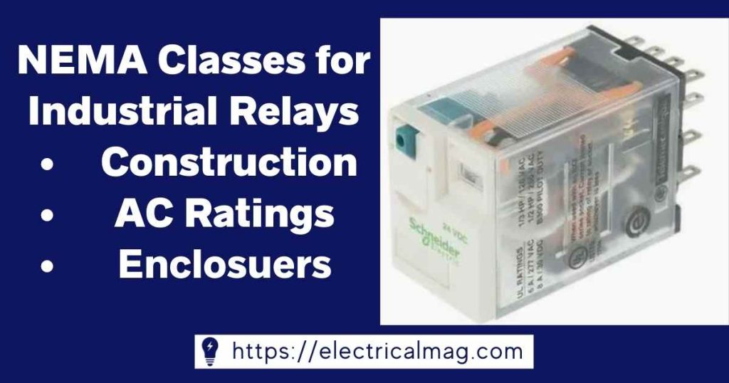
The most common general-purpose relays have a ten-ampere continuous rating. To ensure their optimal performance, contact ratings must meet the following conditions: an ambient temperature of 40°C (104°F); potential differences across the coil of 85-100 percent of the rated value; and frequencies between 25-60 Hz with a potential difference of 120, 240, 480 or 560 volts AC. These requirements are considered to be minimums for reliable operation.
Enclosures
Relays used in industrial applications can either have an enclosure or be open-style construction. Open-style relays are typically installed in control panels with other devices, while enclosed relays are often utilized for special or highly specific applications. Enclosures offer additional protection from dust, dirt, and moisture that could potentially damage the relay and affect its performance. Furthermore, enclosures can also help to protect personnel from electric shock during maintenance, repair, or handling of the relay.
Read More about Relay: Reed Relay